

- FRILO 2012 CRACK PDF
- FRILO 2012 CRACK ARCHIVE
- FRILO 2012 CRACK VERIFICATION
- FRILO 2012 CRACK SOFTWARE
In addition, losses due to relaxation of the prestressing steel are taken into account. In this examination, the loss from creep and shrinkage is determined with the help of previously calculated creep factors and shrinkage strains and with consideration of the reinforcement portions. The pretension effective in the point of examination (load transfer area, stripped insulation) and at the time of examination is taken into account. In this examination, the actions active at that time are examined on the effective structural system in each case. Subsequently, the beginning and the end of the creep stages defined for the girder are examined. You can examine and verify the girder either on freely selectable cross sections or via the automatic processing of a set of sections determined with the help of a grit.Īt the point of examination, the corresponding cross section is generated in line with the shape of the girder, existing recesses, bearing reinforcements and cast-in-place complements.
FRILO 2012 CRACK VERIFICATION
Limitations No consideration of recesses in the verification of shear resistance No calculation of the through-reinforcement for the flange connections Reinforcement Multi-layer pre-tensioned reinforcement, optionally with insulation Multi-layer untensioned reinforcement Straight run of the reinforcement in parallel to the top and/or bottom flange

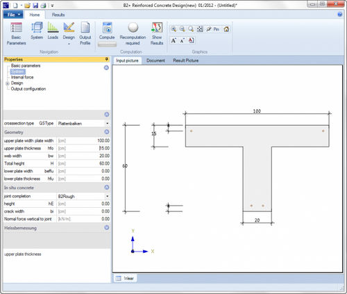
Loading (mainly static, uniaxial without torsion) Uniform linear loads Concentrated loads Concentrated moments Trapezoidal loads Structural systems Single-span girder with/without cantilevers Separate systems for the installed state and the erecting states Auxiliary supports for the pouring of the cast-in-place complement Shapes of cross sections Rectangular T-girder with one or two webs General cross sections (simple symmetrical) Optionally with cast-in-place concrete complement With up to 10 recesses With bearing reinforcements Girders with parallel flanges Symmetrical girders with saddle or groove Asymmetrical girders with saddle or groove Single-pitch roof girders
FRILO 2012 CRACK SOFTWARE
The software application allows you to verify concrete girders that were pre-tensioned in a stressing bed and/or individual cross sections in accordance with the following standards:ĭIN EN /NA 2015-12 Germany PN EN /NA:2010 Poland NORM B : Austria NA to BS EN /A2:2015-07 Great Britain EN 2004/A1:2014 Eurocode, NDP with recommended values Former versions (DIN.) still available.
FRILO 2012 CRACK PDF
Software for structural calculation and designįDC Basic Operating Instructions General instructions for the manipulation of the user interfaceįDC Menu items General description of the typical menu items of Frilo software applicationsįDC Output and printing Output and printingįDC - Import and export Interfaces to other applications (ASCII, RTF, DXF )įCC - the easy-to-use administration module for projects and itemsįDD - document management based on PDF Reinforcing steel definition 25 Recesses 26 Bearings 27 Loads 28 Self-weight 30 Sections 30 Lateral buckling 32 Optional settings 33 Calculate 34 Output 35 Output of the calculation results 35 Utilization 36 Adviser 37 Output settings 39 Text view 39 Selection of the degree of prestressing and suitable reinforcement 41 Reference literature 42 Further information and descriptions are available in the relevant documentations:ĭurability - Creep Coefficient and Shrinkage Strain.pdf" Prestressing steel definition 22 Reinforcing steel 24
FRILO 2012 CRACK ARCHIVE
Documents referring to former standards are available in our document archive at > Service>Documentation >Manuals.Īpplication options 5 Basis of calculation 7 Overview of standards 7 Verifications 8 Definition of the structural system 9 First steps 9 Basic data 11 Cross section 13 Cast-in-place concrete 15 Erection 17 Concrete 18 Concrete properties 18 Shrinkage and creep 19 Prestressing steel 21 Note: The present document describes the Eurocode-specific application.


 0 kommentar(er)
